test uploading a pic in cnblogs
使用以下命令安装
1 | sudo apt install libglu1-mesa-dev freeglut3-dev mesa-common-dev xorg-dev |
不要直接从pdf上复制命令,pdf上的横线符号是错误的,会导致 unable to locate
来自在 Win10 下配置 GAMES101 开发环境(WSL2) - 知乎 (zhihu.com)
1.执行
1 | export LIBGL_ALWAYS_INDIRECT=0 |
2.下载MobaXterm,作为终端启动ropesim
但是,我的MobaXterm中只有一个WSL,上文提到图形界面显示失败的问题并未解决。
下面是通过StackOverflow等摸索而来:
执行
1 | touch ~/.Xauthority |
然后重启MobaXterm,
然后执行
1 | sudo cp ~/.Xauthority /root/ |
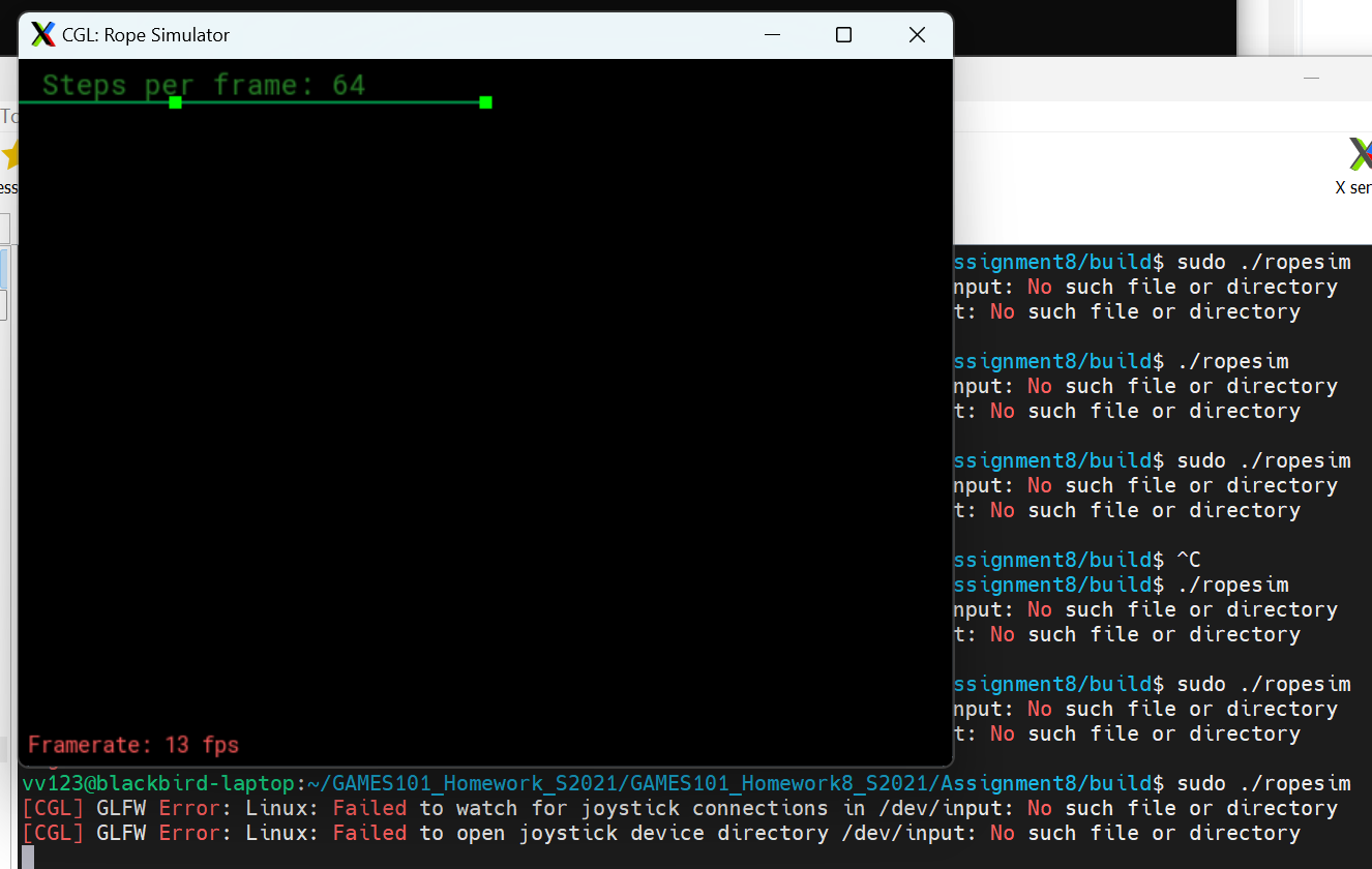
然后使用sudo打开ropesim
1 | sudo ./ropesim |
虽然仍会显示GLFW Error,但能够成功显示窗口。
参考:
关于作业8的一些问题解答 – 计算机图形学与混合现实在线平台 (games-cn.org)
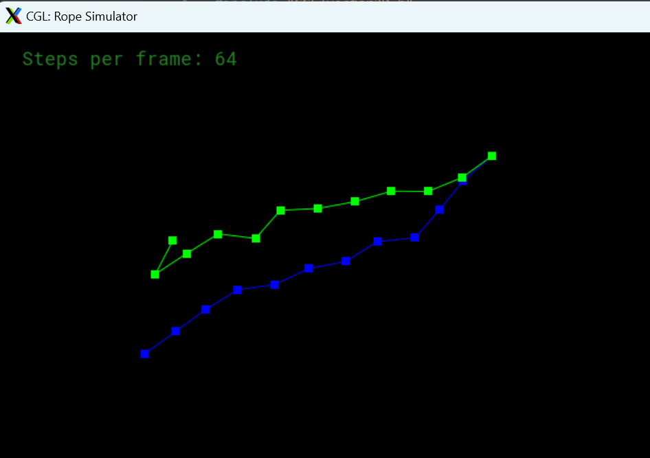
对于显示欧拉法,是正常的,减小步长(如 sudo ./ropesim -s 1024 )可以减缓发散的时间(但还是会发散)
对于Verlet方法,要在计算每个质点后把 m->forces清零,上面simulateEuler函数中已经给出,此处需要自己加上。
1 |
|
通过手写软光栅渲染器加深对计算机图形学基本原理的理解,并练习C++面向对象程序设计。
该项目主要参考Home · ssloy/tinyrenderer Wiki (github.com)编写,使用CMake构建
可以浏览我的历史commit,找到不同进度时提交的代码。
本项目涉及的几乎所有的图形学知识都在GAMES101课程中出现过,推荐将GAMES101作为前置课程,或配合GAMES101的进度一起学习。
使用这个基本框架来生成TGA格式图像:
ssloy/tinyrenderer at 909fe20934ba5334144d2c748805690a1fa4c89f (github.com)
只需 #include "tgaimage.h" ,并在编译时链接tgaimage.cpp即可。
例:在屏幕上将像素(52,41)设置为红色
1 |
|
个人推荐的环境:Clion + CMake。(因为VsCode CMake调试功能实在搞不懂=.=)
涉及导入模型,需要将工作目录设置为工程文件夹


但我的Clion存在tga图像无法加载的bug。在设置->编辑器->文件类型中去掉.tga,然后选择用本地程序打开即可。
使用Bresenham算法绘制线段。
原理:https://en.wikipedia.org/wiki/Bresenham's_line_algorithm
实现参考:https://rosettacode.org/wiki/Bitmap/Bresenham%27s_line_algorithm#C++
建议绘制斜率小于-1,-1到0,0到1,大于1,以及水平和垂直的直线来检验算法正确性。
1 |
|
效果

三维物体模型通常以三角形为基础。为了方便表示点、向量、多边形,写geometry.h。
1 |
|
如何画出实心的三角形?一般来说,有扫描线和边界函数两种算法。
对于多线程的CPU,采用边界函数法更为高效:先找到三角形的矩形包围盒,再逐点判断是否在三角形中
1 | triangle(vec2 points[3]) { |
因此,问题变成了给定三角形的三个点,如何判断点是否在三角形内部
一种最好的办法是,计算给定点关于给定三角形的重心坐标(或者叫面积坐标)。
维基百科:https://zh.wikipedia.org/wiki/%E9%87%8D%E5%BF%83%E5%9D%90%E6%A0%87
简单来说,它表示一个点所对的三条边形成的三角形面积比。如果点在三角形外部,则有一个维度是负的。

由于tinyrenderer的作者写得有些丑陋,我在geometry.h里直接加入了polygon和triangle类,来实现重心坐标计算和点在三角形内的检测
1 | template <class T> |
在main.cpp里绘制实心三角形
1 | //Iterate all points in the rectangular bounding box of triangle, draw if the point is inside |
得到如图效果:

三角形绘制完成后,可以尝试导入作者提供的由三角形构成的人脸模型。
.obj模型文件的格式如下
1 | # List of geometric vertices, with (x, y, z, [w]) coordinates, w is optional and defaults to 1.0. |
目前,我们暂时不关心模型的深度(z坐标),只是将模型正投影到XY平面上,则模型上的点对应的屏幕坐标可以这样简单的计算
1 | screen_coords[j] = Vec2i((v.x+1.)*width/2., (v.y+1.)*height/2.); |
假设光从正前方射向正后方,即光线方向(0,0,-1)。
在这里,我们使用一种简化的亮度计算方法:我们忽略面与光源之间的距离差异,认为正对着光源的面(法线与光线方向相同)最亮,这样就可以计算每个三角形面的单位法向量与光线方向的叉积来代表亮度。
1 | int main(int argc, char** argv) { |
在这种简化下,得到的渲染结果如下:
可以发现,位于口腔中的三角形遮住了嘴唇。下一节课中,我们将考虑深度测试,正确处理多边形的遮挡关系。
深度检测算法的基本原理是,引入一个大小为像素数量的Z-Buffer数组,初始化所有像素点深度为负无穷。
在遍历像素点时,比较当前三角形上点的深度是否小于Z-Buffer的数值,如果小于,则更新该像素并更新Z-Buffer。
为此,我们需要为屏幕坐标增加一维深度(对于上面的人脸设置为模型的z即可)。在drawSolidTriangle()中增加对深度缓冲区的判断。
1 | //Iterate all points in the rectangular bounding box of triangle, draw if the point is inside |
同时,在Triangle2D类中加入depth数组即可
1 | template <class T> |
效果如图所示:
在.obj文件中,有以“vt u v”开头的行,它们给出了一个纹理坐标数组。
The number in the middle (between the slashes) in the facet lines “f x/x/x x/x/x x/x/x” are the texture coordinates of this vertex of this triangle. Interpolate it inside the triangle, multiply by the width-height of the texture image and you will get the color to put in your render.
tinyrender作者提供了漫反射纹理: african_head_diffuse.tga
据此,我们可以给上述人脸模型添加纹理。此时,main函数中drawSolidTriangle函数里不需要再传入颜色,只需要传入intensity即可,另外需要传入当前三角形三个点的纹理坐标uv。
1 | //Iterate all points in the rectangular bounding box of triangle, draw if the point is inside |
model.h和model.cpp需要修改以支持纹理。作者在lesson4的结尾放出了代码。
效果:

这是一个平行投影的结果,损失了一部分真实感,例如,虽然耳朵旁边的头发在xoy平面上不与脸部重叠,但实际上应该被前边的皮肤遮挡,因为人眼/相机本身是“点光源”,而不是“平行光源”,物体发出的光线最终汇聚于一点,也就是所谓的“透视”。下面将引入透视投影:
齐次坐标

简单变换(图来自GAMES101)

逆变换

复合变换

实现矩阵类:
1 | const int DEFAULT_D = 4; |
一个简单投影矩阵的推导:
假设相机位置为(0,0,c)成像平面为z=0,如图

根据三角形相似,x’/c = x/(c-z),即有

同理

为了实现z轴方向上靠近相机的线段被拉伸,远离相机的线段被压缩,投影矩阵具有这样的形式

根据齐次坐标的结果,得到对应的投影点坐标

根据上面的结果,可知r=-1/c。
我们可以得到一个简单情况下的投影矩阵,变换过程如图

在程序中,这个过程用如下方式实现:
1 | screen_coords[j] = hc2v(viewportMatrix * projectionMatrix * v2hc(v)); |
(普通坐标 → 齐次坐标)
世界坐标 → (经投影变换)投影坐标 → (经视口变换)屏幕坐标
(齐次坐标 → 普通坐标)
这里的坐标包含位置(x,y)和深度z,深度交给z-buffer来处理
视口变化的目的是将投影区域映射到[-1,1]^3的立方体中,便于绘制
相关变化的实现:
1 | //Transition between coordinates (vector type) and homogeneous coordinates (matrix type) |
效果

注:TinyRenderer的透视投影与GAMES101处理方式不同,GAMES101是把M[3][2]固定为1,求解M的第三行,而此处是固定第三行为(0 0 1 0),求解M[3][2]。
此处并没有“近平面”的概念,认为n=0,f=c。
下面是GAMES101给出的结果(第三行为0 0 A B):


之前,我们考虑了相机在(0,0,c),朝着-z方向看的情况。
对于任意的相机位置,需要三个向量来确定:相机坐标e,相机指向的点c,向上方向向量u,如图所示:

我们假定相机总是朝着-z方向看,而u朝向正y方向,据此就得到了一个新的坐标系x’y’z’,
下面考虑如何将物体坐标[x,y,z]转化为新坐标系下的[x’,y’,z’]。

首先回顾坐标[x,y,z]的定义,它是三个正交的单位向量i,j,k前面的系数

现在,我们有了新的单位向量i’,j’,k’,那么一定存在矩阵M,使得

我们将OP写成OO’+O’P,与新的单位坐标建立联系:

将[i’,j’,k’]用上面的式子表示,提出[i,j,k]:

左边用[x,y,z]的定义式替换,就得到了[x’,y’,z’]与[x,y,z]的关系

关于look at的推导,此处写的有些混乱
建议参阅https://www.zhihu.com/question/447781866
下面是个人理解:
简单来说,设M是(0, 0, 0),[i,j,k]到eyepos, [i’,j’,k’]的变换矩阵
则M=TR,先旋转后平移
其中旋转矩阵R根据单位向量左乘该矩阵得到新单位向量,很容易得到(此处r,u,v是i’,j’,k’在原坐标系下的坐标)

而T则为原点平移到eye pos的平移矩阵 (C是eyepos)

此为对坐标轴的变换矩阵,即,我们用M计算了新的单位向量在原坐标系下的坐标,而要得到原来单位向量在新坐标系下的坐标,显然应该左乘M的逆矩阵。这样,我们就求得了ModelView矩阵。
据此,编写lookup实现modelview的计算
1 | Vec3f light_dir = Vec3f(0, 0, -1).normalize(); |
效果 目前有点bug

为了处理光照,我们将模型进行坐标变换后,如果模型提供了每个面的法向量,还需要将法向量也进行变换。
此处有一个结论:模型上的坐标通过矩阵M进行仿射变换,那么模型的法向量的变换矩阵是M的逆矩阵的转置。
证明:考虑平面方程 Ax+By+Cz=0,它的法向量是(A,B,C) ,写成矩阵形式为:

在两者之间插入M的逆和M:

由于坐标均为列向量,把左边写成转置形式:

因此,如果对坐标(x,y,z)做变换M,要满足原来的直线方程,对法向量的变换矩阵为M的逆矩阵的转置(或者转置再求逆,转置和求逆是可交换的,证明略)
本节主要分为两大部分:重构代码,实现不同的shaders。
再尝试用自己之前的屎山适配Shader部分后,我放弃了,直接使用作者写的geometry。内容大部分都很直观,值得注意的是
1 | template<size_t LEN,size_t DIM,typename T> vec<LEN,T> embed(const vec<DIM,T> &v, T fill=1) { |
这两个模板的作用,分别是将低维向量拓展到高维(不足补1)、高维向量投影到低维(截取前LEN个坐标),在涉及其次坐标和普通坐标的转换时多次用到。

Shader包含顶点着色和片元着色两个部件,将其抽离出来,可以使得我们通过修改Shader即可实现各种不同的渲染效果,而无需改动其他代码。
在gl.h中,定义Shader的基本结构。不同Shader的通过继承基类重写两个虚函数来实现
1 | struct IShader { |
其中,iface是面的编号,而nthvert是顶点编号(对于三角形为0,1,2)。
例如,一个简单的GouraudShader,vertex通过顶点法向量与光照的点乘计算三角形每个顶点的光照,而fragment通过重心坐标插值计算三角形区域中所有像素的颜色。
1 | struct GouraudShader : public IShader { |
所得的效果如图

我们可以轻松地修改着色器,实现不同的渲染效果,如将颜色设置为6个梯度的橙色:
1 | virtual bool fragment(Vec3f bar, TGAColor &color) { |
效果:

纹理着色器
接下来,我们可以实现漫反射纹理。只需要修改Shader添加纹理映射项即可。
1 | struct TextureShader : public IShader { |
效果

法线着色器
事实上,纹理图像中不止可以储存颜色,还可以储存法线方向、温度等等信息。通过纹理给出每个点的法线方向,就能实现表明的凹凸起伏效果。此时,纹理图像的RGB值不再储存颜色,而是用于储存法线,如下图。

上节课的结尾,我们提到了“模型上的坐标通过矩阵M进行仿射变换,那么模型的法向量的变换矩阵是M的逆矩阵的转置”这一结论,根据这个结论,就可以直接在顶点着色器中分别计算顶点和法向量经过投影后的结构
1 | struct NormalShader : public IShader { |
效果:

Phone模型着色器

根据Phone光照模型,物体的真实光照可以近似为环境光+漫反射+高光。据此,我们可以进一步得出更加真实的着色器。
高光的计算如图所示:

已知物体表明法向量为n,入射光为l,两者夹角为a,假设所有向量都被归一化,设反射光为r,则有l+r=2n cosa ,可求得反射光r=2n cosa - l = 2n(n·l)-l。反射光
1 | struct PhoneShader : public IShader { |
按照环境光5+自身颜色*(1漫反射+0.6高光),得到的效果如下

我们可以试试其他的配比系数,如10 + c[i]*(2 * diff + 1.5*spec

另外,我们还可以到master分支找其他的模型,尝试渲染效果


首先回顾路径追踪的原理,如下图

wo是射向眼镜(相机)的光线,包含来自光源的直接光照ws,来自其他物体的间接光照wi两部分。
在实现path tracing时,我们考虑的是黄色线的方向,即光线从相机射向p点(实际上是从p点射向相机),然后通过多次随机采样从p点射出(实际上是射向p点)的光线得到该像素点的真实颜色。
为了提高效率,将射向p的光线分为ws(光源)和wi(其他物体)计算。由于wi、ws分开计算,因此如果ws被物体挡住,或者wi打到光源均不计算。
wi需要递归计算,通过神奇的Russian Roulette在减少递归层数的同时保持光照的期望不变。
然后按照作业指南上的伪代码写就可以了

return t_enter <= t_exit && t_exit >= 0; 就可以TARGET_LINK_LIBRARIES(RayTracing pthread)就好。1 | // change the spp value to change sample ammount |
1 | // Implementation of Path Tracing |
Welcome to Hexo! This is your very first post. Check documentation for more info. If you get any problems when using Hexo, you can find the answer in troubleshooting or you can ask me on GitHub.
1 | $ hexo new "My New Post" |
More info: Writing
1 | $ hexo server |
More info: Server
1 | $ hexo generate |
More info: Generating
1 | $ hexo deploy |
More info: Deployment